Double Disc Valve
Tai&Chyun double-disc anti-abrasion gate valve uses double discs, single/double-side seal, sealed with ceramic and tungsten steel, with excellent mechanical and wear-resistant properties and hardness up to 60~90HRC. Such design solves the short life time issue due to sealing surface abrasion and erosion by continuous scouring material mixed with compressed air.
Principle of Operation
When the compressed air enters from the upper intake port, the valve stem drives plates to move downward, the valve closes. Air enters from the down intake port; stem drives plate to move upward, the valve opens. Spring is added between the plate and seat to ensure they always close tightly, at the same time enable plats move gently vertically. Such design could compensate for thermal expansion and contraction of the valve parts, and can overcome any influence of fluctuating back pressure on the seal and prevent particulate medium entering sealing surface. In the process of opening and closing, valve plates could self-rotate, as a result sealing surfaces could be grinded, and polished. Additionally, eddy current would be produced due to inlet/outlet channel is off centering to valve body, and such eddy would purge the valve cavity automatically. All these characteristics contribute to the superior long life time of valve, providing a reliable guarantee for your system.
Parameters
| Parameter |
Value |
| Nominal Diameter |
DN50-DN300 |
| Nominal Pressure |
1.0MPa |
| Actuator Working Pressure |
0.4-0.6MPa |
| Working Temperature |
≤200oC (High Temp. Type ≤450oC) |
| Applicable Media |
Fly ash, ash and slag, dry dust, solid particles, and other abrasive and corrosive materials. |
Characteristics
- No barrier in inlet/outlet port, compressed air automatic blowing valve cavity, less fouling phenomenon.
- Wear-resistance and long service life.
- Arbitrary installation position and angle. Compact structure, easy installation.
- Seals can be replaced, cost savings.
- Good effect of high temperature applications. (Max. 450oC)
Installation, Use and Maintenance
- Please read this guide carefully before installation, and check valve type, diameter and technical parameters.
- Welding on flange after installation is forbidden, so as not to damage the valve seals. Proper distance should be set aside according to valve. Plus both sides of the flange gasket to adjust the connection.
- Pipe and valve should be kept coaxial. Flange surface is not allowed to have a great deflection flange to ensure that the valve clamping and working properly. Tighten the bolts should be done symmetrical.
- In order to prolong life, improve work efficiency, when installing this valve please ensure upright. If the condition is not allowed the install angle should be adjusted (i.e. 45o), but the cylinder downward is forbidden.
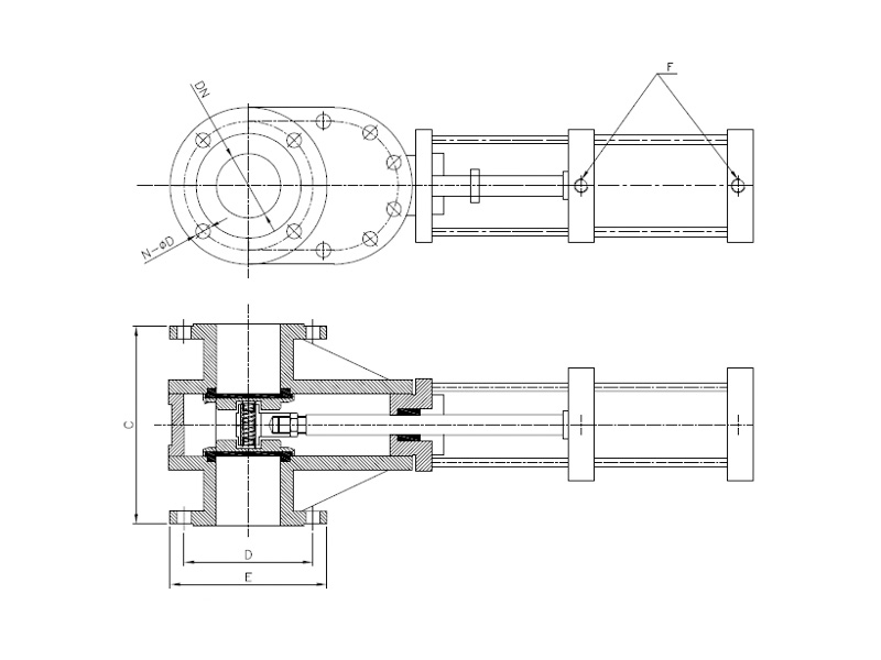
Dimensions and Actuator Size